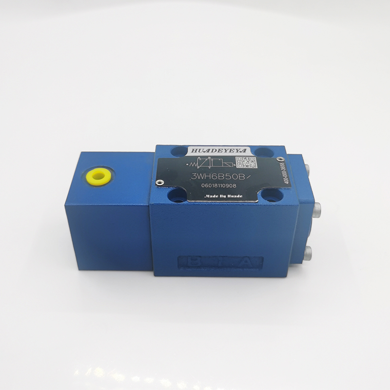
How does a hydraulic directional control valve work?
Hydraulic directional control valves play a critical role in hydraulic systems, enabling precise control over fluid flow direction. These valves determine the path of hydraulic fluid, directing it to specific hydraulic actuators for desired movements. In this article, we will explore the working principles of a hydraulic directional control valve, understanding how it facilitates precise fluid flow control and regulates the operation of hydraulic systems.
Valve Position and Flow Paths: A hydraulic directional control valve typically has multiple flow paths that determine the direction of fluid flow. The valve can be in various positions, including neutral, closed, or open positions. In the neutral position, all flow paths are blocked, preventing fluid flow. When the valve is shifted to an open position, it creates a passage for fluid flow, allowing it to reach the desired hydraulic actuators. The specific positions and flow paths depend on the valve's design, configuration, and actuation mechanism.
Spool or Poppet Movement: The movement of the spool or poppet within the valve body controls the opening and closing of flow paths. In spool valves, the spool is typically cylindrical, with channels or grooves machined into it. By shifting the spool's position, the channels align with different ports, enabling fluid flow in specific directions. In poppet valves, spring-loaded poppets seal or open specific passages as they are pushed against or pulled away from their seats. The movement of the spool or poppet is determined by the actuation mechanism.

Actuation Mechanism: The actuation mechanism of a hydraulic directional control valve determines how the spool or poppet is moved to control fluid flow. There are various types of actuation mechanisms, including manual, solenoid-operated, and pilot-operated.
a. Manual Actuation: In manual actuation, an operator manipulates a lever, knob, or handle to shift the valve's position. This movement directly influences the position of the spool or poppet, opening or closing flow paths accordingly. Manual actuation provides immediate control over fluid flow direction and is often used in applications where real-time adjustments are required.
b. Solenoid-Operated Actuation: Solenoid-operated valves use an electromagnetic coil to generate a magnetic field. When an electric current is applied to the coil, the magnetic field attracts or repels the spool, shifting its position. This movement opens or closes flow paths, allowing or blocking fluid flow. Solenoid-operated valves provide remote control capability and can be easily integrated into automated systems.
c. Pilot-Operated Actuation: Pilot-operated valves utilize hydraulic pressure to control the movement of the spool. A pilot pressure is applied to specific chambers within the valve, exerting force on the spool or poppet. This force determines the valve's position and, consequently, the fluid flow paths. Pilot-operated valves offer precise control and can handle high pressures, making them suitable for complex hydraulic systems.
Fluid Flow Control and Actuator Operation: By shifting the valve's position or actuation mechanism, specific flow paths are opened or closed, controlling the direction of fluid flow. When flow paths are open, hydraulic fluid is directed to the desired hydraulic actuators, such as cylinders or motors. This fluid flow activates the actuators, initiating the desired movements, such as extending or retracting a cylinder or rotating a motor. The precise control over fluid flow direction enables accurate and repeatable operation of hydraulic systems.
Safety and Pressure Relief: Hydraulic directional control valves often incorporate safety features, such as pressure relief valves. These valves protect the hydraulic system from excessive pressure buildup, preventing potential damage or hazards. Pressure relief valves are designed to open when the pressure exceeds a predetermined limit, diverting excess fluid flow back to the reservoir or another path, ensuring system stability and safety.
Conclusion:
Hydraulic directional control valves are vital components in hydraulic systems, governing the flow direction of hydraulic fluid. Through the movement of the spool or poppet and the actuation mechanism, these valves open or close specific flow paths, directing fluid to the desired hydraulic actuators. Understanding the working principles of hydraulic directional control valves allows for accurate selection, installation, and operation of these valves in various applications. By controlling fluid flow with precision, Huade hydraulic directional control valves contribute to the reliable and efficient operation of hydraulic systems across industries such as manufacturing, construction, agriculture, and transportation.
152
0
0


Comments
All Comments (0)